API 6D Ball Valve
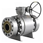
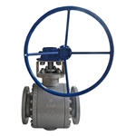
Relia is a API 6D ball valve manufacturer with API 6D certificate, supplying API 6D floating ball valve and trunnion mounted ball valves.
API 6D ball valves are fully in compliance with the requirements for the the design,manufacturing, assembly, testing, and documentation of API 6D specifications.
- Valve Type
- Floating/Trunnion Ball Valve
- Standard
- API 6D
- Size
- 2"-48"
- Pressure Rating
- Class 150-2500
- Unit Price
- $50-20000
- Certificate
- API 6D


API 6D Ball valves shall be of solid one-piece spherical construction with a closure member that rotates on an axis perpendicular to the direction of flow.
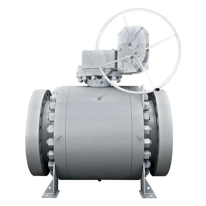
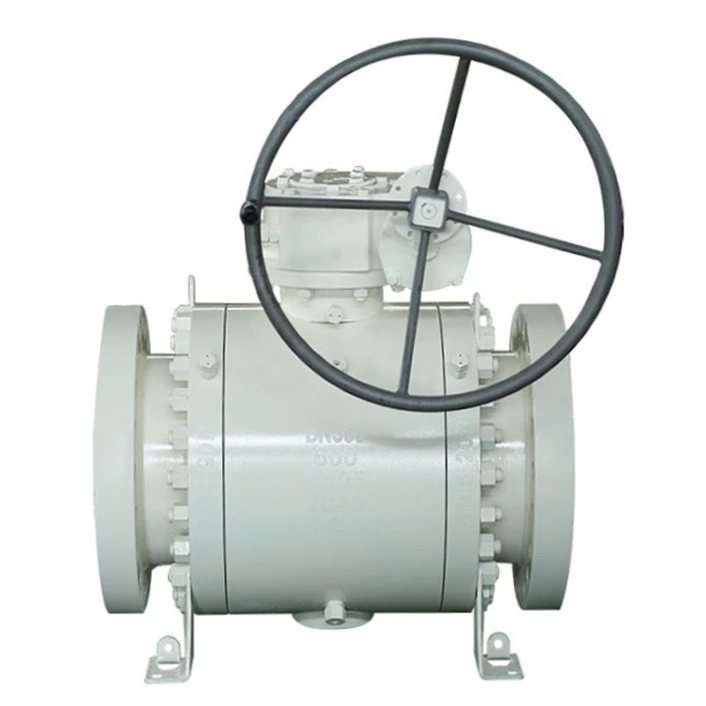
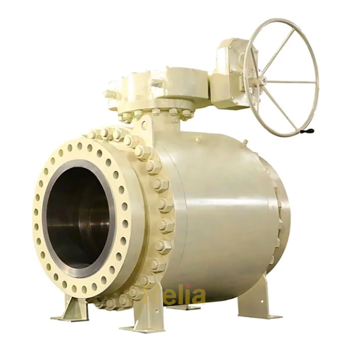
Typical configurations for API 6D ball valves with flanged or welding ends are shown, in Figure B.2, Figure B.3, Figure B.4, and Figure B.5.
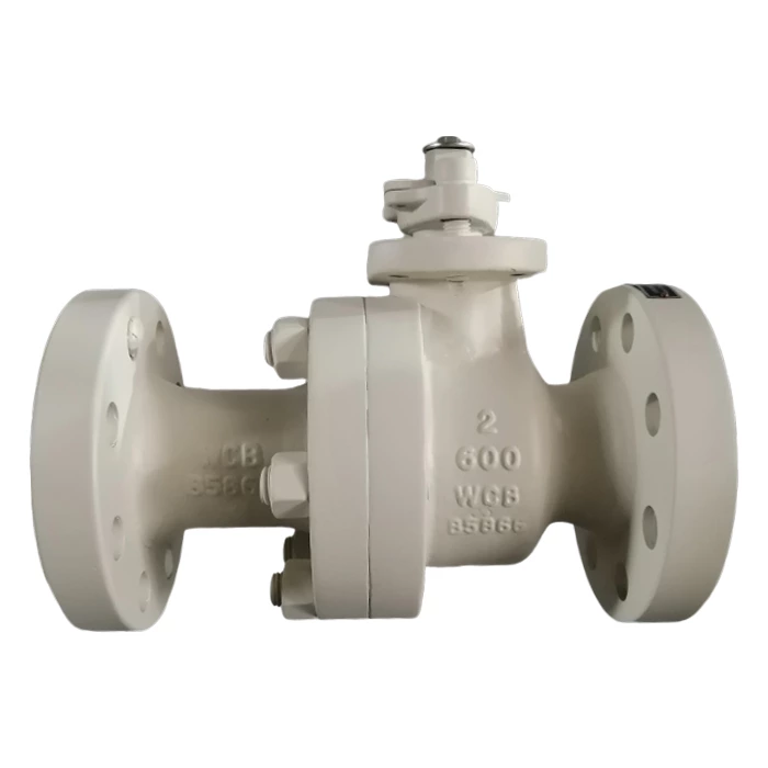
Figure B.2-API 6D Floating Ball Valve
Assembly Drawing
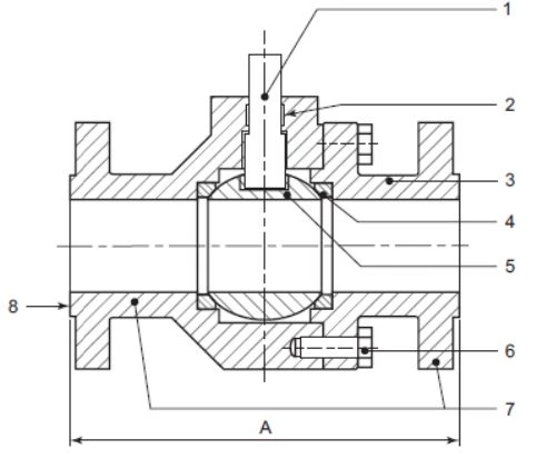
Main Part
| Part No. | Part Name |
| 1 | stem |
| 2 | stem seal |
| 3 | end connector |
| 4 | seat ring |
| 5 | ball |
| 6 | body bolting |
| 7 | raised face |
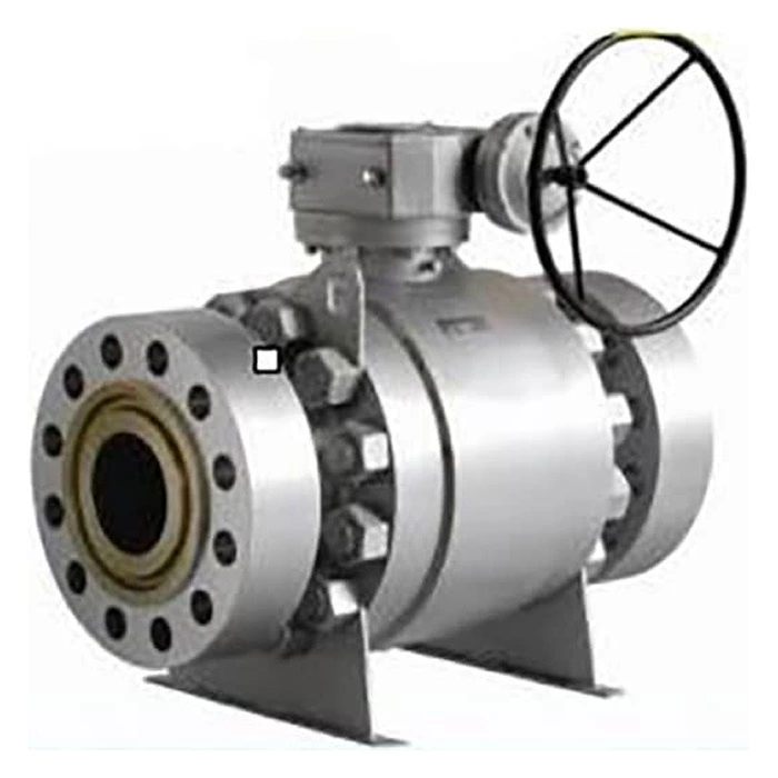
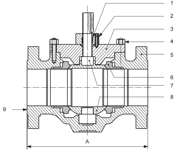
Figure B.3-API 6D Trunnion Mounted Ball Valve (Side Entry )
Assembly Drawing
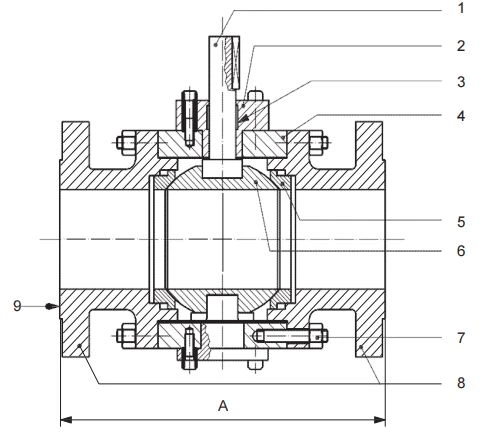
Main Part
| Part No. | Part Name |
| 1 | stem |
| 2 | body cover |
| 3 | stem seal |
| 4 | body |
| 5 | seat ring |
| 6 | ball |
| 7 | body bolting |
| 8 | end connector |
| 9 | raised face |
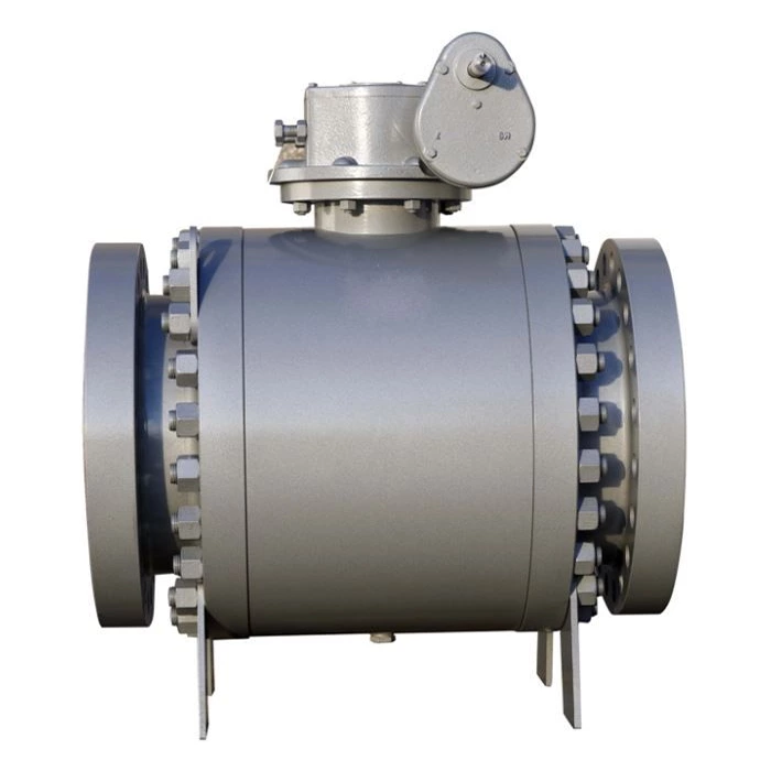
Figure B.3-API 6D Trunnion Mounted Ball Valve (Top Entry )
Assembly Drawing
Main Part
| Part No. | Part Name |
| 1 | stem seal |
| 2 | body cover |
| 3 | bonnet |
| 4 | body bolting |
| 5 | body |
| 6 | seat ring |
| 7 | stem |
| 8 | ball |
| 9 | raised face |
API 6D specification defines the requirements for the design,manufacturing, materials, welding, quality control,assembly,testing, marking,documentation and process controls of axial, ball,check,gate,plug valves for application in the petroleum and natural gas industries.
Valve Bore
Full-opening Valves
Full-opening valves shall be unobstructed in the fully opened position and shall have an internal minimum circular opening for categorizing bore size as specified in Table 1. When pipe is used in the construction of the valves, the pipe shall meet the tolerances of the applicable pipe specification. Closure member and seat dimensions shall meet Table 1.
Valves with a noncircular opening through the closure member shall not be identified as full opening.
Reduced-opening Valves with Circular Opening
Reduced-opening valves with a circular opening through the closure member shall be supplied with a minimum bore as follows:
― valves NPS 4 (DN 100) to NPS 12 (DN 300): one size below nominal size of valve with bore according to Table 1,
― valves NPS 14 (DN 350) to NPS 24 (DN 600): one or two sizes below nominal size of valve with bore according to Table 1.
― valves sizes less than NPS 4 (DN 100) or greater than NPS 24 (DN 600) in conformance with K.3
EXAMPLE An NPS 16 (DN 400) Class 1500 reduced-opening ball valve has an allowable minimum bore of 11.30 in.(287.0 mm).
Table 1—Minimum Bore for Full-opening Valves
| NPS | DN | Minimum a Bore by Class, in. (mm)b | |||
| Class 150 to 600 | Class 900 | Class 1500 | Class 2500 | ||
| ½ | 15 | 0.50 (12.7) | 0.50 (12.7) | 0.50 (12.7) | 0.50 (12.7) |
| ¾ | 20 | 0.75 (19.0) | 0.75 (19.0) | 0.75 (19.0) | 0.75 (19.0) |
| 1 | 25 | 0.98 (25.0) | 0.98 (25.0) | 0.98 (25.0) | 0.98 (25.0) |
| 1¼ | 32 | 1.25 (31.8) | 1.25 (31.8) | 1.25 (31.8) | 1.25 (31.8) |
| 1½ | 40 | 1.50 (38.0) | 1.50 (38.0) | 1.50 (38.0) | 1.50 (38.0) |
| 2 | 50 | 1.93 (49.0) | 1.93 (49.0) | 1.93 (49.0) | 1.65 (42.0) |
| 2½ | 65 | 2.44 (62.0) | 2.44 (62.0) | 2.44 (62.0) | 2.05 (52.0) |
| 3 | 80 | 2.91 (74.0) | 2.91 (74.0) | 2.91 (74.0) | 2.44 (62.0) |
| 4 | 100 | 3.94 (100.0) | 3.94 (100.0) | 3.94 (100.0) | 3.42 (87.0) |
| 6 | 150 | 5.91 (150.0) | 5.91 (150.0) | 5.67 (144.0) | 5.16 (131.0) |
| 8 | 200 | 7.91 (201.0) | 7.91 (201.0) | 7.55 (192.0) | 7.04 (179.0) |
| 10 | 250 | 9.92 (252.0) | 9.92 (252.0) | 9.41 (239.0) | 8.78 (223.0) |
| 12 | 300 | 11.93 (303.0) | 11.93 (303.0) | 11.30 (287.0) | 10.43 (265.0) |
| 14 | 350 | 13.15 (334.0) | 12.67 (322.0) | 12.40 (315.0) | 11.50 (292.0) |
| 16 | 400 | 15.16 (385.0) | 14.69 (373.0) | 14.17 (360.0) | 13.11 (333.0) |
| 18 | 450 | 17.16 (436.0) | 16.65 (423.0) | 15.98 (406.0) | 14.72 (374.0) |
| 20 | 500 | 19.17 (487.0) | 18.54 (471.0) | 17.87 (454.0) | 16.50 (419.0) |
| 22 | 550 | 21.18 (538.0) | 20.55 (522.0) | 19.69 (500.0) | — |
| 24 | 600 | 23.19 (589.0) | 22.44 (570.0) | 21.50 (546.0) | — |
| 26 | 650 | 24.92 (633.0) | 24.29 (617.0) | 23.38 (594.0) | — |
| 28 | 700 | 26.93 (684.0) | 26.18 (665.0) | 25.23 (641.0) | — |
| 30 | 750 | 28.94 (735.0) | 28.03 (712.0) | 27.00 (686.0) | — |
| 32 | 800 | 30.66 (779.0) | 29.92 (760.0) | 28.74 (730.0) | — |
| 34 | 850 | 32.68 (830.0) | 31.81 (808.0) | 30.50 (775.0) | — |
| 36 | 900 | 34.41 (874.0) | 33.66 (855.0) | 32.24 (819.0) | — |
| 38 | 950 | 36.42 (925.0) | 35.59 (904.0) | — | — |
| 40 | 1000 | 38.43 (976.0) | 37.63 (955.8) | — | — |
| 42 | 1050 | 40.16 (1020.0) | 39.61 (1006.0) | — | — |
| 48 | 1200 | 45.90 (1166.0) | 45.24 (1149.0) | — | — |
| 54 | 1350 | 51.65 (1312.0) | — | — | — |
| 56 | 1400 | 53.54 (1360.0) | — | — | — |
| 60 | 1500 | 57.40 (1458.0) | — | — | — |
| FOOTNOTES a There is no upper size limit for a valve bore. b The millimeter dimension is the inch dimension multiplied by 25.4 and rounded to one decimal place. “—“ = No identified minimum bore. | |||||
Pressure and Temperature Rating
Pressure–temperature ratings for class-rated valves shall conform to the rating table for the applicable material group per ASME B16.34 or for carbon steel per MSS-SP 44.
The pressure–temperature rating applied shall be based on the material group of the valve end connector. Where the valve ends are made from material in two different groups, the material with the lower pressure–temperature rating shall determine the rating.
NOTE Different material or material forms may be used for body and bonnet or cover parts within the same valve.
All metallic pressure-containing and pressure-controlling parts shall be designed to meet the identified valve pressure–temperature rating.
The manufacturer shall determine any limits on the maximum allowable operating pressure and shall identify theminimum and maximum design temperatures resulting from the nonmetallic parts used.
Pressure Testing Procedure
Written test procedures that identify test methodology, test durations and acceptance criteria shall be developed and maintained for all pressure testing performed in conformance to this specification.
Each valve shall be tested in the fully assembled condition to the manufacture’s procedures prior to shipment. Pressure testing shall be carried out before external coating of the valve.
NOTE If the valve has been previously pressure tested to the requirements of this specification, subsequent repeat hydrostatic and gas testing may be performed without removal of the valve external coating.
Testing shall be performed in the sequence as listed in order of 10.3 to 10.4.5. The backseat test that is only applicable to valves per 10.2 shall be performed either immediately before or immediately after the hydrostatic shell test in 10.3.


Leave Us Your Info
Could you please kindly fulfill the following information when enquiring:
Valve type (ball, gate, globe, check etc.), valve size, pressure class, valve material, and end connection (flanged, butt welding etc.)