BS 5351: Steel ball valves for the petroleum, petrochemical and allied industries
BS 5351 Standard specifies the valve seat and body pressure/temperature ratings, and the design, including materials, dimensions, operation, performance, testing and marking, of straightway steel ball valves having specified wall thickness, an
antistatic feature and fire tested design.
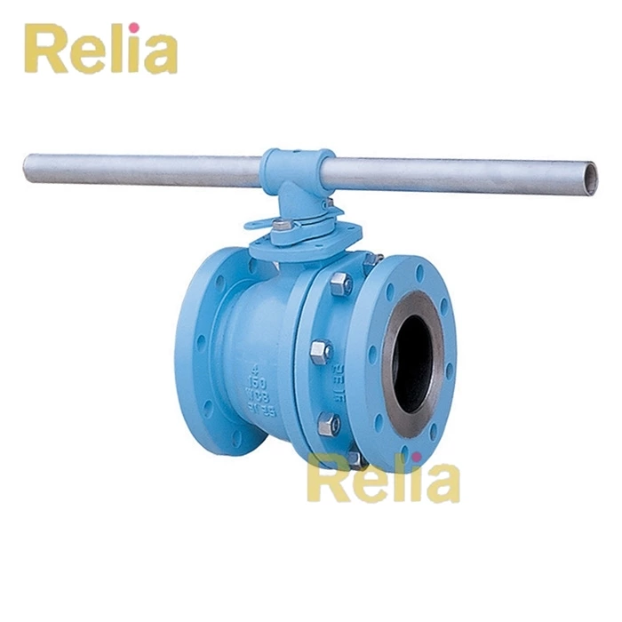
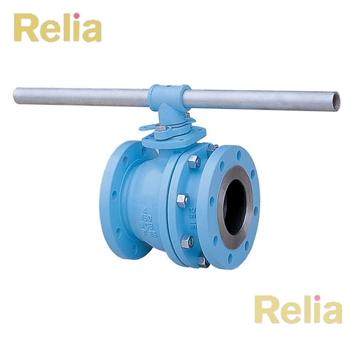
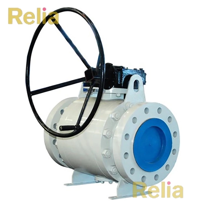
BS 5351 specifies full bore valves and reduced bore valves of one piece or split body construction with balls which may be seat supported or trunnion supported. The ranges of valves covered by this standard are given in Table 1 and Table 2 (see also clauses 4 and 5).
This standard does not cover the installation of ball valves.
NOTE 1-The titles of publications referred to in this standard are listed on page 22 and the inside back cover.
NOTE 2- The information to be supplied by the purchaser at the time of his enquiry/order is given in the form of a data sheet in Appendix A.
3- Valve patterns
Valves shall be full bore or reduced bore (see Figure 1) of short or long pattern, where applicable, as given in Table 6 and BS 2080.
4- Nominal sizes
Valves shall be of nominal sizes (DN) or (in) or threaded end sizes according to the type of end fitting given in Table 1.
5 Pressure designation
Pressure designations of valves shall be as given in Table 2.
6 Pressure/temperature ratings
Pressure/temperature seat ratings of valves shall be as given in Table 3. With the exception of body seat rings and primary soft seals, all valve components shall be capable of withstanding the pressure/temperature ratings as specified in BS 1560-2, BS 4504-1 or Table 4, as appropriate.
Table 1 — Nominal sizes of valves according to end fitting
| Nominal size | Valve end fittings (see notes 1 and 2) | |||||
| DN (see note 3) |
Inch | Flanged end | Butt-weld end | Socket-weld end | Extended weld end | Threaded end size (see note 4) |
| 8 | 1/4" | - | - | - | - | 1/4" |
| 10 | 3/8" | - | - | - | - | 3/8" |
| 15 | 1/2" | √ | √ | √* | √ | 1/2" |
| 20 | 3/4" | √ | √ | √* | √ | 3/4" |
| 25 | 1" | √ | √ | √* | √ | 1" |
| 32 | 1-1/4" | √ | √ | √* | √ | 1-1/4" |
| 40 | 1-1/2" | √ | √ | √ | √ | 1-1/2" |
| 50 | 2" | √ | √ | √ | √ | 2" |
| 65 | 2-1/2" | √ | √ | - | - | - |
| 80 | 3" | √ | √ | - | - | - |
| 100 | 4" | √ | √ | - | - | - |
| 150 | 6" | √ | √ | - | - | - |
| 200 | 8" | √ | √ | - | - | - |
| 250 | 10" | √ | √ | - | - | - |
| 300 | 12" | √ | √ | - | - | - |
| 350 | 14" | √ | √ | - | - | - |
| 400 | 16" | √ | √ | - | - | - |
NOTE 1 "√" indicates valve size covered by this standard available both in (DN) and (in) nominal size. "√*" indicates for Class 600 valves only.
NOTE 2 Valve sizes shown in parentheses are non-preferred (see foreword).
NOTE 3 When nominal sizes DN 8 and DN 10 are used in tables, these sizes refer only to valves with threaded end sizes of 1/4 and 3/8 repectively.
NOTE 4 Threaded end valves are available only in the sizes given in this column. Designations for sizes are given in ANSI/ASME B1.20.1 or BS 21, as appropriate.
Table 2 — Pressure designations of valves according to end fitting
| Pressure designation |
Valve end fittings | ||||
| Flanged end | Butt weld end | Socket weld end | Extended weld end | Threaded end | |
| Nominal pressure (PN) |
10 | 10 | - | - | - |
| 16 | 16 | - | - | - | |
| 25 | 25 | - | - | - | |
| 40 | 40 | - | - | - | |
| Class | 150 | 150 | 800 only | 800 only | 800 only |
| 300 | 300 | - | - | - | |
| 600 | 600 | - | - | - | |
Note: Calss 800 Applies to forged or bar stock bodies only.
Table 3 — Minimum pressure/temperature seat ratings for ball valves
| Nominal size of valve (DN) |
Service temperature (°C) | ||||||||||
| -30 to 40 | 50 | 75 | 90 | 100 | 125 | 150 | 175 | 200 | 230 | ||
| Full bore | Redueced bore | Minimum non-shock pressure (bar) | |||||||||
| 8 to 20 | 8 to 25 | 69 | 66 | 56 | 51 | 47 | 38 | 29 | 20 | 11 | 0 |
| 25 to 65 | 32 to 80 | 50 | 49 | 48 | 48 | 47 | 38 | 29 | 20 | 11 | 0 |
| 80 to 100 | 100 to 150 | 42 | 42 | 42 | 42 | 39 | 32 | 24 | 17 | 9 | 0 |
| 150 | 200 to 250 | 31 | 31 | 31 | 31 | 29 | 23 | 18 | 12 | 7 | 0 |
| 200 to 400 | 300 to 400 | 21 | 21 | 21 | 21 | 20 | 16 | 12 | 8 | 5 | 0 |
NOTE 1- The pressure/temperature ratings given in Table 3 are based on seat rings made from PTFE resins without fillers, of
virgin material completely free of reclaimed processed material (see 10.3).
NOTE 2- See Table 1 for equivalent nominal size (in).
NOTE 3- 1 bar = 100 kN/m 2 = 100 kPa.
Table 5 — Nominal pressure and class ratings and nominal size
| 1 | 2 | 3 |
| Pressure rating | Nominal size range | |
| PN | Class | |
| 10 | 150 | 15 to 400 |
| 16 | 150 | 15 to 400 |
| 25 | 300 | 15 to 400 |
| 40 | 300 | 15 to 400 |
NOTE - See Table 1 for equivalent nominal size (in)
7- Dimensions
7.1 Flanged-end valves
7.1.1 Flange dimensions shall comply with BS 1560-2 for Class rated valves or BS 4504-1 for PN rated valves.
7.1.2 Face-to-face dimensions shall be in accordance with BS 2080. Valves having flanges complying with BS 4504-1 with nominal pressure (PN) ratings as given in Table 5 shall have the same face-to-face dimensions as valves with flanges of the
corresponding class ratings. The applicable nominal size range is also given.
7.2 Butt-weld-end valves
End-to-end dimensions shall be in accordance with:
a) Table 6 for PN 10, PN 16, Class 150 and PN 25, PN 40 and Class 300 valves;
b) BS 2080 for Class 600 valves.
NOTE- The details for the weld preparation for butt-weld-end valves are not a requirement of this standard but attention is
drawn to Appendix B which gives details of various weld-end preparations and it is incumbent upon the purchaser to specify a particular weld-end preparation, if required (see Figure 3 and Figure 4).
7.3 Socket-weld-end valves
Socket-weld-end dimensions shall be as given in Table 7.
7.4 Extended-weld-end valves
The overall length of weld-end valves when fitted with extended ends shall be 400 ± 1 mm; valves of nominal sizes DN 15 to DN 40 shall have ends square or prepared for welding.
NOTE - Valves of nominal size DN 50 should have bevelled ends in accordance with Appendix B which gives details of various weld-end preparations and it is incumbent upon the purchaser to specify a particular weld-end preparation, if required (see Figure 3 and Figure 4).
Table 9 — Minimum ball and body port diameters PN 10, PN 16, Class 150, PN 25, PN 40, Class 300, Class 600 and Class 800
| Nominal size | Minimum diameter (mm) | |||
| Reduced bore valves | Full bore valves | |||
| DN | Inch | PN10 up to and including PN40 and Class 150 to 800 | PN 10 up to and including PN 40 and Class 150 | Class 600 and 800 |
| 8 | 1/4" | 6 | 6 | 6 |
| 10 | 3/8" | 6 | 9 | 9 |
| 15 | 1/2" | 9 | 12.5 | 12.5 |
| 20 | 3/4" | 12.5 | 17 | 17 |
| 25 | 1" | 17 | 24 | 24 |
| 32 | 1-1/4" | 23 | 30 | 30 |
| 40 | 1-1/2" | 28 | 37 | 37 |
| 50 | 2" | 36 | 49 | 49 |
| 65 | 2-1/2" | 50 | 64 | 64 |
| 80 | 3" | 57 | 75 | 75 |
| 100 | 4" | 75 | 98 | 98 |
| 150 | 6" | 98 | 148 | 148 |
| 200 | 8" | 144 | 198 | 198 |
| 250 | 10" | 187 | 248 | 245 |
| 300 | 12" | 228 | 298 | 295 |
| 350 | 14" | 266 | 335 | 325 |
| 400 | 16" | 305 | 380 | 375 |
11 Pressure testing
All valves shall be pressure tested in accordance with BS 6755-1 and for the minimum test durations given in Table 14, and additionally:
a) the shell test shall be a hydrostatic test and there shall be no visually detectable leakage from the valve including the valve stem seals;
b) the seat test shall be either pneumatic or hydrostatic.
NOTE 1- If a particular type of seat test is required, i.e. pneumatic or hydrostatic, the purchaser should state the requirement in the enquiry and/or order (see Appendix A).
NOTE 2- The hydrostatic seat test is an optional test for soft seated ball valves. The purchaser should state any requirement for hydrostatic pressure tests on soft seated ball valves in the enquiry and/or order (see Appendix A).
NOTE 3- It should be noted that soft seated valves, when hydrostatically tested, might have a reduced performance capability in some subsequent services at low differential pressures. In these cases the manufacturer should be consulted.
c) the seat test acceptance level for all valves shall be leakage rate A, i.e. no visually detectable leakage.
If a production pressure test certificate is issued it shall contain a statement by the manufacturer confirming that the valves have been tested in accordance with this standard, and stating the actual pressures and medium used in the tests.
NOTE - If a test certificate is required this should be specified by the purchaser on the enquiry and/or order for the valves
(see Appendix A).
Table 14 — Pressure test durations
| Nominal valve size | Minimum test durations: hydrostatic or pneumatic |
||
| Shell test | Seat test | ||
| DN | Inch | minutes | minutes |
| ≤100 | ≤4 | 2 | 2 |
| 150≤250 | 6≤10 | 5 | 5 |
| 300≤400 | 12≤16 | 15 | 5 |
Related Information
API 6D: Specification for Valves in the petroleum and natural gas industries
API 608: Metal Ball Valves-Flanged, Threaded, and Welding Ends


