BS 5352: Steel wedge gate, globe and check valves 50 mm and smaller
1 Scope
BS 5352 Standard specifies requirements for forged, cast or bar stock steel wedge gate, globe stop and check valves with flanged, screwed, socket-weld or butt-weld ends, in nominal sizes 50 mm (2 in) and smaller in classes 150, 300, 600, 800 and 1500 of the following types.
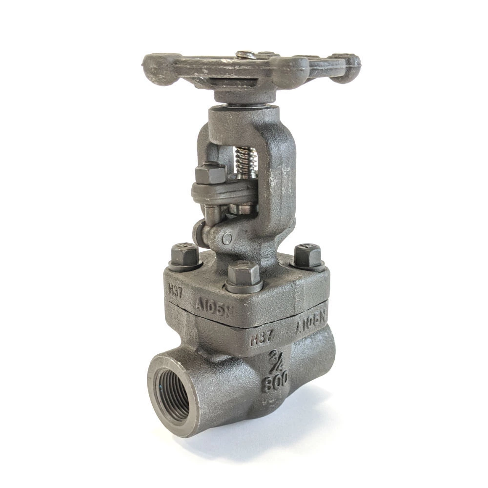
a) Wedge gate valves, with outside screw and yoke, rising stem, bolted or welded bonnet and bolted gland:
1) reduced bore, compact (class 800 only); and 800 only;
2) standard bore.
b) Wedge gate valves, with inside screw, rising stem and handwheel, bolted or welded bonnet and gland nut, for use at temperatures up to 425 °C only, and with screwed and socket-weld ends:
1) reduced bore, compact (class 800 only);
2) standard bore (class 1500 only).
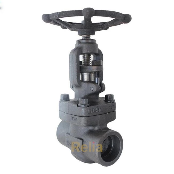
c) Globe valves, including screw down check valves (straight angle or oblique pattern), outside screw and yoke, rising stem and handwheel, bolted or welded bonnet and bolted gland, plug or needle type disk:
1) reduced bore;
2) standard bore.
d) Globe valves, including screw down check valves (straight angle or oblique pattern), inside screw, rising stem and handwheel, bolted or welded bonnet, gland nut and plug or needle type disc, for use at temperatures up to 425 °C only:
1) reduced bore;
2) standard bore.
NOTE Screwed and socket-weld ends classes 800 and 1500 only.
e) Bellows-sealed valves:
1) wedge gate, with outside screw and yoke, rising stem, bolted or welded bonnet, screwed or bolted gland, and reduced bore (compact);
2) globe (straight angle or oblique pattern), with outside screw and yoke, rising stem, bolted or welded bonnet, screwed or bolted gland, plug or needle type disk, and reduced or standard bore.
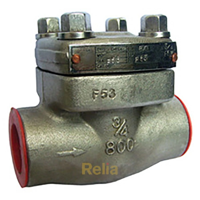
f) Check valves, with bolted, welded or union cover:
1) piston type (for angle or horizontal flow);
2) ball type (for angle or horizontal flow);
3) ball type (for vertical flow).
NOTE The terms “vertical”, “horizontal” and “angle” relate to the axis of the body ends.
4 Pressure classification
BS5352 standard applies to valves of the following class ratings:
150; 300; 600; 800; 1500.
NOTE The number in these class ratings represents the primary service pressure rating of the valve in lbf/in 2 .
5 Pressure/temperature ratings
5.1 General. The pressure/temperature ratings applicable to valves covered by this standard shall be in accordance with Tables PE-1 to PE-12 of BS 1560-2:1970 for the particular shell material except that class 800 valves shall be in accordance
with Table 1
NOTE 1 There is, however, a temperature restriction on certain trim materials (see 33.4 and Table 11).
NOTE 2 Inside screw valves are subject to a service temperature restriction (see 5.2).
NOTE 3 Valves with a bellows seal may be subject to reduced pressure/temperature ratings compared with standard valves (see 5.3).
NOTE 4 Where valves complying with the requirements of this standard are to be used at service temperatures below – 30 °C, reference should be made to BS 3351. Service temperature refers to the temperature of the fluid in the line at the valve.
NOTE 5 For pressure/temperature ratings for valves supplied for use in piping systems with flanges in accordance with BS 4504-1 see A.2.
5.2 Inside screw valves. The following types of valve shall not be used at service temperatures exceeding 425 °C:
a) inside screw wedge gate valves;
b) inside screw globe and screw down check valves.
6 Nominal sizes
Valves of the following nominal sizes are specified in this standard:
| DN (mm) | Inch | DN (mm) | Inch |
| 8 | 1/4" | 25 | 1" |
| 10 | 3/8" | 32 | 1-1/4" |
| 15 | 1/2" | 40 | 1-1/2" |
| 20 | 3/4" | 50 | 2" |
7 End types
Table 3 specifies the types of ends available for each class and size of valve covered by this standard.
Table 1 - Pressure/temperature ratings for class 800 screwed and socket-weld end valves
| Service temperature |
Maximum non-shock service pressure rating |
||
| Carbon steel |
1-1/4% chromium- 1-1/2% molybdenum steel |
5 % chromium 1/2% molybdenum steel |
|
| °C | bar | bar | bar |
| -30 to 38 | 138 | 138 | 138 |
| 50 | 137 | 137 | 137 |
| 75 | 135 | 135 | 135 |
| 100 | 133 | 133 | 133 |
| 125 | 132 | 132 | 132 |
| 150 | 130 | 130 | 130 |
| 175 | 129 | 129 | 129 |
| 200 | 128 | 128 | 128 |
| 225 | 125 | 125 | 125 |
| 250 | 122 | 122 | 122 |
| 275 | 116 | 116 | 116 |
| 300 | 110 | 110 | 110 |
| 325 | 103 | 103 | 103 |
| 350 | 97 | 97 | 97 |
| 375 | 89 | 91 | 91 |
| 400 | 81 | 86 | 86 |
| 425 | 71 | 80 | 80 |
| 450 | 59 | 74 | 74 |
| 454 | 55 | 73 | 73 |
| 475 | 47 | 68 | 68 |
| 500 | 34 | 63 | 63 |
| 525 | 22 | 55 | 55 |
| 540 | 15 | 50 | 50 |
NOTE 1 The above pressure/temperature ratings are the minimum requirement and valves having ratings in excess of these may be obtained from individual manufacturers.
NOTE 2 The use of valves at temperatures where the creep strength might be the limiting criterion is subject to the establishment of a design life.
a 1 bar = 10 5 N/mm 2 = 100 kPa.
b Primary service pressure.
Table 3 — End type availability according to class and size of valve
| Size, DN | Class | ||||
| 150 | 300 | 600 | 800 | 1500 | |
| 8 | - | - | - | Screwed | - |
| 10 | - | - | - | Screwed | - |
| 15 | Flanged, BW | Flanged, BW | Flanged, BW | Screwed, Socket Weld | Flanged, BW, Screwed, SW |
| 20 | Flanged, BW | Flanged, BW | Flanged, BW | Screwed, Socket Weld | Flanged, BW, Screwed, SW |
| 25 | Flanged, BW | Flanged, BW | Flanged, BW | Screwed, Socket Weld | Flanged, BW, Screwed, SW |
| 32 | Flanged, BW | Flanged, BW | Flanged, BW | Screwed, Socket Weld | Flanged, BW, Screwed, SW |
| 40 | Flanged, BW | Flanged, BW | Flanged, BW | Screwed, Socket Weld | Flanged, BW, Screwed, SW |
| 50 | Flanged, BW | Flanged, BW | Flanged, BW | Screwed, Socket Weld | Flanged, BW, Screwed, SW |
9 Shell
9.1 General. The shell shall be designed to resist the maximum pressure ratings, to minimize pressure loss and to minimize corrosive and erosive effects.
9.2 Body and bonnet wall thickness. With the exception of pipe ends, the minimum wall thickness of body and bonnet, measured at any point, shall be not less than that specified in Table 4.
Table 4 — Minimum body and bonnet wall thickness (excluding pipe ends)
| DN | Inch | Minimum body and bonnet wall thickness | ||
| Class 150, 300, 600 and 800 | Class 1500 | |||
| Standard bore | Reduced bore | Standard bore | ||
| 8 | 1/4" | 3.3 | 3.0 | - |
| 10 | 3/8" | 4.1 | 3.3 | - |
| 15 | 1/2" | 4.8 | 4.1 | 5.2 |
| 20 | 3/4" | 5.6 | 4.8 | 6.1 |
| 25 | 1" | 5.8 | 5.6 | 6.7 |
| 32 | 1-1/4" | 6.1 | 5.8 | 7.5 |
| 40 | 1-1/2" | 7.1 | 6.1 | 7.8 |
| 50 | 2" | 7.5 | 7.1 | 8.6 |
9.3 Port diameter and seat bore. The body end ports shall be circular. The port diameter and seat bore shall comply with the values specified in Table 5.
9.4 Body ends for screwed-end and socket-weld end valves
9.4.1 General. The outside diameter or dimension across flats of body ends for all types of screwed-end and socket-weld end valves shall be not less than the minimum values specified in Table 6 for classes 800 and 1500.
9.4.2 Socket-weld ends. Socket-weld end valves shall have circular ends and end faces machined square to the axis. Socket details shall comply with the requirements of BS 3799.
Table 5 — Minimum port diameter and seat bore
| Size | Minimum port diameter and seat bore | |||||||
| DN | inch | Globe needle valves | Class 1500, 300, and 800 | Class 1500 | ||||
| Wedge gate valve | Globe and check valves | Wedge gate valve | Globe and check valves | |||||
| Standard bore | Reduced bore | Standard bore | Reduced bore | Standard bore | Reduced bore | |||
| mm | mm | mm | mm | mm | mm | mm | ||
| 8 | 1/4" | 3.0 | 6.0 | - | 6.0 | - | - | - |
| 10 | 3/8" | 3.0 | 9.0 | 6.0 | 9.0 | 6.0 | - | - |
| 15 | 1/2" | 5.0 | 12.0 | 9.0 | 12.0 | 9.0 | 11.5 | 11.0 |
| 20 | 3/4" | 6.5 | 18.0 | 12.0 | 17.5 | 12.0 | 15.0 | 14.5 |
| 25 | 1" | 8.5 | 23.0 | 18.0 | 22.5 | 17.5 | 19.5 | 19.0 |
| 32 | 1-1/4" | 11.0 | 30.0 | 23.0 | 29.5 | 22.5 | 28.0 | 27.0 |
| 40 | 1-1/2" | 15.0 | 36.0 | 30.0 | 35.0 | 29.5 | 32.0 | 31.0 |
| 50 | 2" | 18.5 | 46.5 | 36.0 | 45.5 | 35.0 | 40.0 | 37.5 |
9.4.3 Screwed ends. Screwed-end valves shall be of an appropriate shape to facilitate tightening and shall have either hexagonal or circular ends. The ends shall project clear of the body to permit the effective use of a pipe wrench. For screwed-end valves with hexagonal ends the across flats dimension shall be suitable for use with open-ended spanners complying with the requirements of BS 192.
Thread lengths shall comply with the requirements of BS 3799. The thread shall be in accordance with either API Standard 5B or ANSI B2.1 unless otherwise stated by the purchaser.
9.5 End flanges. End flanges shall comply with the requirements of BS 1560-2. The type of flange facing shall be specified by the purchaser and shall be one of the types shown in Figure 1 of BS 1560-2:1970.
End flanges shall be either:
a) forged; or
b) cast integral with the body; or
c) welded to the body, if agreed between manufacturer and purchaser.
The welds of end flanges attached by butt welding shall comply with the requirements of BS 3351. The attachment of flanges by other welding processes shall be the subject of agreement between the manufacturer and the purchaser.
9.6 Face-to-face and end-to-end dimensions.
Face-to-face dimensions for flanged-end valves and end-to-end dimensions for butt-weld end valves and ring-joint end valves shall conform to the dimensions specified in BS 2080.
9.7 Butt-weld ends. Butt-weld ends shall conform to the details specified in Appendix D. For butt-weld ends, the purchaser shall state either:
a) the pipe schedule number and outside diameter; or
b) the pipe wall thickness and outside diameter.
Table 6 — Minimum outside diameter or dimension across flats of body ends
| Size | Minimum outside diameter or dimension across flats of body ends (mm) | ||
| DN | Inch | Class 800 | Class 1500 |
| 8 | 1/4" | 22 | - |
| 10 | 3/8" | 25 | - |
| 15 | 1/2" | 32 | 38 |
| 20 | 3/4" | 38 | 45 |
| 25 | 1" | 45 | 55 |
| 32 | 1-1/4" | 55 | 62 |
| 40 | 1-1/2" | 62 | 75 |
| 50 | 2" | 75 | 80 |
12 Direction of flow
If check valves of the vertical or angle pattern are used, the flow shall be in the upward direction.
NOTE- For the purposes of this standard, any line with a slope (upward or downward) of 5° or less is deemed to be horizontal.
Globe valves shall be designed to be suitable for installation in either direction of flow but the preferred direction of flow for globe valves shall be from under the disc.
14 Wedge
The wedge of wedge gate valves shall be of the solid type with integral or deposited faces. The sharp outer edges of the seating surfaces shall be removed to prevent scoring of the body seating surfaces.
The wedge shall be guided in the body to prevent rotation and to ensure re-entry between the seats.
The wedge shall be provided with a slot at the top to receive the button or teehead of the stem. The minimum values of wear travel shall be in accordance with Table 7.
Table 11a — Required production pressure tests
| Valve type | Required test | ||||
| Shell | Backseat | Seat | Low pressure seat | ||
| Hydrostatic | Hydrostatic | Hydrostatic | Pneumatic | Hydrostatic | |
| Gate Valve | Required | Required | Required | Required | Required |
| Globe Valve | Required | Required | Required | Required | Required |
| Check Valve | Required | N/A | Required | N/A | N/A |
| Bellows sealed gate and globe |
Required | Required | Required | Required | N/A |
Related Information
API 602: Gate, Globe, and Check Valves for Sizes DN 100 and Smaller
