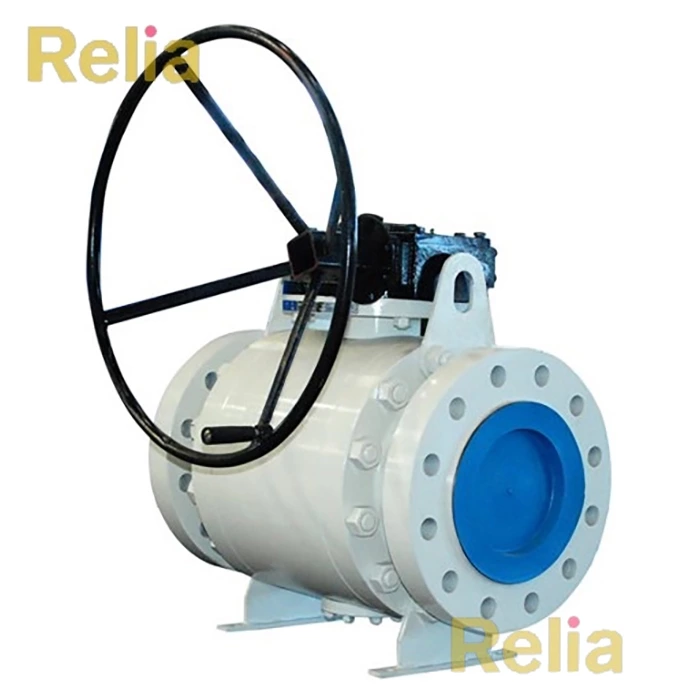
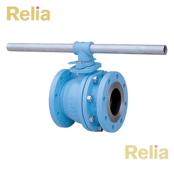
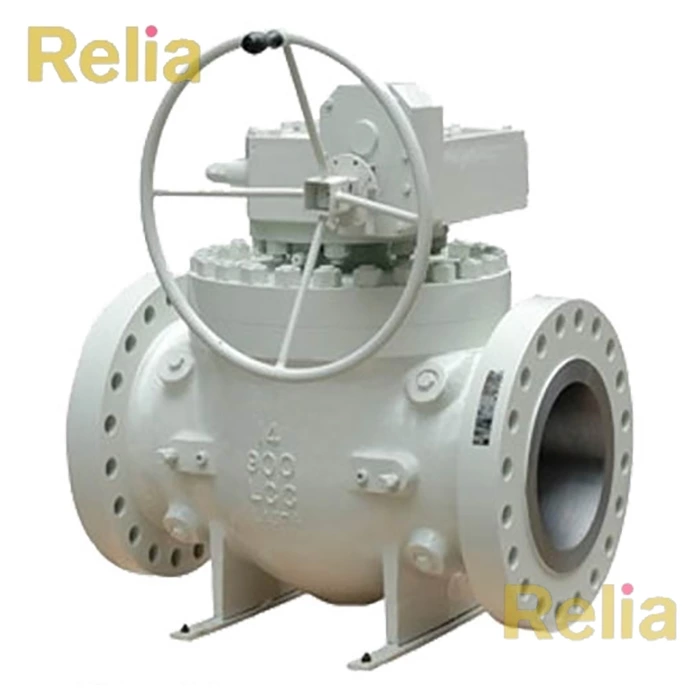
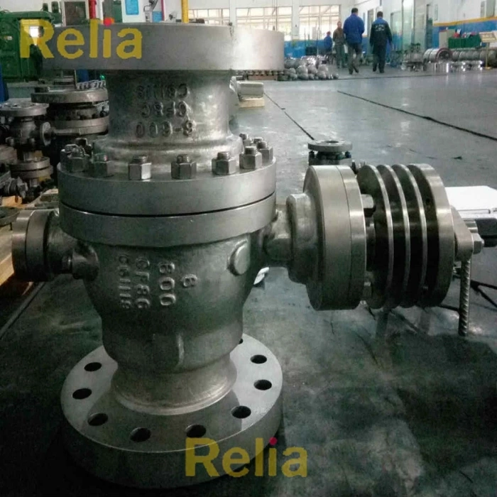
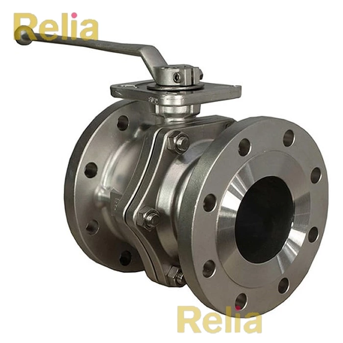
ISO 17292: Metal ball valves for petroleum, petrochemical and allied industries
1 - Scope
BS EN ISO 17292 Standard specifies the requirements for a series of metal ball valves suitable for petroleum, petrochemical, natural gas plants, and related industrial applications.
It covers valves of the nominal sizes DN
— 8; 10; 15; 20; 25; 32; 40; 50; 65; 80; 100; 150; 200; 250; 300; 350; 400; 450; 500
corresponding to nominal pipe sizes NPS
— ¼; ⅜; ½; ¾; 1; 1¼; 1½; 2; 2½; 3; 4; 6; 8; 10; 12; 14; 16; 18; 20;
and applies for pressure designations
— Class 150; 300; 600; 800 (Class 800 applies only for valves with reduced bore and with threaded and socket welding end);
— PN 16; 25; 40.
It includes provisions for testing and inspection and for valve characteristics as follows:
— flanged and butt-welded ends, in sizes 15 u DN u 500 (½ u NPS u 20);
— socket welding and threaded ends, in sizes 8 u DN u 50 (¼ u NPS u 2);
— body seat openings designated as full bore, reduced bore and double reduced bore;
— materials.
4 - Pressure/temperature ratings
4.1 Valve rating
The service pressure/temperature rating applicable to valves specified in this International Standard shall be the lesser of the shell rating (see 4.2) or the seat rating (see 4.3).
4.2 Shell rating
4.2.1 The pressure/temperature ratings applicable to the valve pressure containing shell (the pressure boundary elements — e.g. body, body cap, trunnion cap, cover, body inserts) shall be in accordance with those specified in the pressure/temperature tables of either ASME B16.34, Standard Class for Class-designated valves, or EN 1092-1 for PN-designated valves.
4.2.2 The temperature for a corresponding shell pressure rating is the maximum temperature that is permitted for the pressure containing shell of the valve. In general, this maximum temperature is that of the contained fluid. The use of a pressure rating corresponding to a temperature other than that of the contained fluid is the responsibility of the user.
For temperatures below the lowest temperature listed in thepressure/temperature tables (see 4.2.1), the service pressure shall be no greater than the pressure for the lowest listed temperature. Consideration should be given to the loss of ductility and impact strength of many materials at low temperature.
4.3 Seat and seal rating
4.3.1 Non-metallic elements, e.g. seats, seals, or stem seals may impose restrictions on the applied pressure/temperature rating. Any such restriction shall be shown on the valve identification plate in accordance with 7.4.
4.3.2 The design shall be such that, when either polytetrafluoroethylene (PTFE) or reinforced PTFE is used for seats, the minimum valve pressure/temperature rating shall as specified in Table 1.
4.3.3 Seat ratings for other seat materials shall be the manufacturer’s standard; however, the assigned valve service pressure/temperature rating shall not exceed that of the valve shell.
Table 1 — Minimum seat pressure/temperature rating
| Temperature °C |
PTFE seats | Reinforced PTFE seats | ||||||
| Floating ball | Trunnion | Floating ball | Trunnion | |||||
| DN ≤ 50 |
50<DN ≤ 100 |
DN>100 | DN>50 | DN ≤ 50 |
50<DN ≤ 100 |
DN>100 | DN>50 | |
| NPS≤2 | 2<NPS ≤ 4 |
NPS>4 | NPS>2 | NPS ≤ 2 |
2<NPS ≤ 4 |
NPS>4 | NPS>2 | |
| -29 to 38 | 69.0 | 51.0 | 19.7 | 51.0 | 75.9 | 51.0 | 19.7 | 51.0 |
| 50 | 63.6 | 47.1 | 18.2 | 47.1 | 70.4 | 47.8 | 18.4 | 47.8 |
| 75 | 53.3 | 39.1 | 15.2 | 39.2 | 59.9 | 40.4 | 15.6 | 40.4 |
| 100 | 43.0 | 31.3 | 12.1 | 31.3 | 49.4 | 33.1 | 12.8 | 33.1 |
| 125 | 32.7 | 23.3 | 9.1 | 23.3 | 38.9 | 25.8 | 10.0 | 25.8 |
| 150 | 22.4 | 15.4 | 6.1 | 15.4 | 28.3 | 18.4 | 7.2 | 18.4 |
| 175 | 12.1 | 7.5 | 3.0 | 7.5 | 7.3 | 11.1 | 4.4 | 11.1 |
| 200 | — | — | — | — | 5.2 | 3.7 | 1.6 | 3.7 |
| 205 | — | — | — | — | 2.3 | 1.0 | 2.3 | |
For a given PN or Class designation, the assigned valve pressure/temperature ratings shall not exceed the shell ratings,
(see 4.2).
a Polytetrafluoroethylene seats.
b Consult the manufacturer for maximum design temperature rating of the valve seats.
c Pressure in bar (1 bar = 0,1 MPa = 10 5 Pa; 1 MPa = 1 N/mm 2
Table 2 — Cylinder diameter for categorizing bore size
| DN | NPS (Inch) | Minumum bore diameter | |||
| Full bore | Reduced bore | Double reduced bore | |||
| PN 10, 16, 25 and 40 | — | PN: All | PN: All | ||
| Class 10 and 300 | Class 600 | Class: All | Class: All | ||
| 8 | 1/4" | 6 | 6 | 6 | N/A |
| 10 | 3/8" | 9 | 9 | 6 | N/A |
| 15 | 1/2" | 11 | 11 | 8 | N/A |
| 20 | 3/8" | 17 | 17 | 11 | N/A |
| 25 | 1" | 23 | 24 | 17 | 14 |
| 32 | 1-1/4" | 30 | 30 | 23 | 18 |
| 40 | 1-1/2" | 37 | 37 | 27 | 23 |
| 50 | 2" | 49 | 49 | 36 | 30 |
| 65 | 2-1/2" | 62 | 62 | 49 | 41 |
| 80 | 3" | 74 | 75 | 55 | 49 |
| 100 | 4" | 98 | 98 | 74 | 62 |
| 150 | 6" | 148 | 148 | 98 | 74 |
| 200 | 8" | 198 | 194 | 144 | 100 |
| 250 | 10" | 245 | 241 | 186 | 151 |
| 300 | 12" | 295 | 291 | 227 | 202 |
| 350 | 14" | 325 | 318 | 266 | 230 |
| 400 | 16" | 375 | 365 | 305 | 250 |
| 450 | 18" | 430 | 421 | 335 | 305 |
| 500 | 20" | 475 | 453 | 375 | 335 |
NOTE 1 - N/A signifies that valves having this configuration are not within the scope of this International Standard.
NOTE 2 - For Class 800, only valves having reduced port are within the scope of this International Standard.
5 - Design
5.1 Flow passageway
The flow passageway includes the circular seat opening in the ball and the body runs leading thereto. The body runs are the intervening elements that link the seat opening to the end connection, e.g. to the thread end, weld end or socket end or to the end-flange. Collectively, the flow passageway through the ball and body runs is referred to as the flow passageway.
The bore is categorized in this International Standard as full bore, reduced bore and double reduced bore. The minimum bore for each category shall be such that a hypothetical cylinder having a diameter in accordance with Table 2 can be passed through.
5.2 Body
5.2.7 Anti-static design
Valves shall incorporate an anti-static feature that ensures electrical continuity between the stem and body of valves DN ≤ 50, and between the ball, stem and body of larger valves. The anti-static feature shall have electrical continuity across the discharge path with a resistance not exceeding 10 Ω from a power source not exceeding 12 V d.c. when type tested on a new, dry, as-built valve after pressure testing and cycling of the valve at least five times.
5.2.8 Anti-blow-out stem
The valve design shall be such that the stem seal retaining device is not the sole means used to retain the stem. The design shall ensure that, while under pressure, the stem is not ejected from the valve by the disassembly of valve external parts, e.g. gland and gland flange bolting. See Annex B.
5.2.9 Ball-stem construction
5.2.9.1 The valve design shall be such that if a failure occurs either at the stem-to-ball connection or any part of the stem within the pressure boundary, no portion of the stem is ejected when the valve is under pressure.
5.2.9.2 Both the stem-to-ball connection and all of that part of the stem within the pressure boundary, shall be designed to exceed the torsional strength of the stem external to the packing by at least 10 %.
5.2.9.3 The stem and the connection between the stem and the ball shall be designed to preclude permanent deformation or failure of any part when a force applied to the direct operating lever or the operational means of a manual gear operator, whichever is furnished with the valve, transmits a torque to the valve stem equal to the greater of either
a) 20 N⋅m, or
b) twice the manufacturer’s recommended torque.
5.2.9.4 The manufacturer’s recommended torque shall be based on clean, dry air or nitrogen at a differential pressure equal to the maximum differential service pressure rating of the valve.
5.2.10 Ball construction
The ball shall have a cylindrical bore and shall be of a solid, one-piece or two-piece construction. Other constructions, such as cored cavity, sealed cavity, or hollow ball, may be furnished only if agreed to by the purchaser.
5.2.11 Operating means
5.2.11.1 Valves that are solely manually operated, i.e. without an attached gear or power assist device, shall be fitted with lever-type handles unless otherwise specified by the purchaser.
5.2.11.2 Gear operators, when specified or required to meet the operating force requirements of 5.2.11.3, shall be provided with handwheels for actuation.
5.2.11.3 Unless otherwise specified by the purchaser, the length of the lever type handle or the diameter of the manual gear handwheel shall be sized so that the applied input force to open or close the valve does not exceed 360 N at the torque value specified in 5.2.9.3.
5.2.11.4 For lever-operated valves, position stops shall be provided at both the full open and full closed positions.
5.2.11.5 Valves shall be designed to close when the lever or handwheel is turned in a clockwise direction.
5.2.11.6 Handwheels on manual gear operators shall be marked to indicate either the direction of opening or closing.
5.2.11.7 Lever-type handles shall be mounted with the handle parallel to the ball bore. If the purchaser specifies round or oval direct operating handwheels, a permanent means of indicating the open and closed positions shall be provided.
5.2.11.8 Lever or manual gear box handwheel design shall be such that the lever or gearbox indicating means do not assemble in other than the correct configuration for indicating the open and closed positions.
5.2.11.9 An indication of the position of the flow passageway through the ball shall be integral with the valve stem. This indication may be by a permanent marking on the stem or by a shaping of the stem.
5.2.11.10 Levers, handwheels, and other operating mechanisms shall be fitted to the valve such that they can be removed and replaced without affecting the integrity of the stem or body seal or retention of the stem.
8 Testing and inspection
8.1 Pressure tests
8.1.1 General
Each valve shall be given a shell pressure test, and a seat closure test in accordance with the requirements of ISO 5208 except as modified herein. Sealing compounds, greases or oils shall be removed from seating surfaces prior to pressure testing. It is permissible, however, for a film of oil that is not heavier than kerosene to be applied to prevent metal-to-metal sealing surfaces from galling.
8.1.2 Shell test
8.1.2.1 The shell test shall be at a pressure no less than 1,5 times the pressure corresponding to the valve 38 °C pressure rating. If the valve design includes an adjustable stem seal, it shall be adjusted so as to maintain the shell test pressure.
8.1.2.2 The duration of the shell test — the minimum period of time that the shell test pressure is to be sustained — shall be in accordance with Table 7.
8.1.2.3 Over the duration of the shell test, there shall be no visually detectable leakage through either the shell wall or any of the gasket seals.
Table 7 — Test duration
| Valve size range | Minimum test duration | |
| Shell test | Seat test | |
| DN≤50 | 15 | 15 |
| 65≤DN≤150 | 60 | 60 |
| 200≤DN≤300 | 120 | 120 |
| 350≤DN≤500 | 300 | 120 |
8.1.3 Closure tightness test
8.1.3.1 For valve designs having resilient seats, the closure tightness test shall be a gas test with the test gas at a pressure between 400 kPa (4 bar) and 700 kPa (7 bar). For floating ball designs, the test method shall be one that fills the body cavity between the seats and the body ball chamber with test gas so as to ensure that no seat leakage can escape detection. For trunnion mounted ball valves of upstream sealing design, the test method shall be one that measures leakage across the upstream seat. For trunnion-mounted valves of downstream sealing design, the test method shall be one that measures leakage across the downstream seat.
8.1.3.2 For valve designs having metal or ceramic seats, the closure tightness test shall be a liquid test with the test fluid at a pressure not less than 1,1 times the rated pressure at 38 °C (100 °F). For floating ball designs, the test method shall be one that fills the body cavity between the seats and the body ball chamber with test liquid so as to ensure that no seat leakage can escape detection. For trunnion-mounted valves of upstream sealing design, the test method shall be one that measures leakage across the upstream seat.
For trunnion-mounted valves of downstream sealing design, the test method shall be one that measures leakage across the downstream seat.
8.1.3.3 The applicable closure test of 8.1.3.1 and 8.1.3.2 shall be applied one flow direction at a time for each seating direction.
8.1.3.4 The duration of the closure test — the minimum period of time that the test pressure is to be sustained for the purpose of obtaining a closure leakage measurement — shall be in accordance with Table 7.
8.1.3.5 Over the duration of the gas closure test, the maximum permitted leakage rate past the seats shall be in accordance with Table 8.
Table 8 — Maximum allowable seat leakage
| Valve size range | Maximum allowable seat leakage rate | ||
| Gas test, resilient seats |
Liquid test, metal or ceramic seats |
||
| mm 3 /s | drops/s | ||
| DN≤50 | 0 | 6.3 | 0.1 |
| 65≤DN≤150 | 0 | 12.5 | 0.2 |
| 200≤DN≤300 | 0 | 20.8 | 0.4 |
| 350≤DN≤500 | 0 | 29.2 | 0.5 |
Note - The valve manufacturer may choose either method of quantifying liquid leakage. It is recognized that the unit conversions are inexact.
8.1.3.6 Visual evidence of leakage through the ball, behind the seats or past shaft seals is not permitted. There shall be no structural damage as a result of the closure test. Plastic deformation of resilient seats or seals is not considered to be structural damage.
8.1.3.7 For the purposes of the gas closure test, zero leakage is defined as 3 mm 3 (1 bubble) over the duration of the test.
NOTE - It is recognized that the unit conversions are inexact.
